rampart abuse (and use)
An initial guide to Rampart, mainly bytebeats
Since rampart is more platform than any given instrument, this overview tries to cover ground that isnt’ just relevant to the bytebeats sketch.
First, a view to the bytebeats sketch and at the end the Multi function generator (derived from code for Modulove’s Synclfo).
But, we’ll start with which interface bits play a role in the default bytebeats sketch.
- 5, pushbutton and encoder: rotate to increase, decrease frequency. push and turn to double or halve freq. short button pushes (1,2 or 3) change the bank of programs (there are three)
- 6, volume/filter
- 15/16 are program back and forward buttons
- 10, controlvoltage inputs 3,6,7 which are averaged with to the controls …
- a b & c, being the 3 parameters of every bytebeat formula.
Play around :)
At the bottom of the page are firmware update instructions and initial info on how to program.
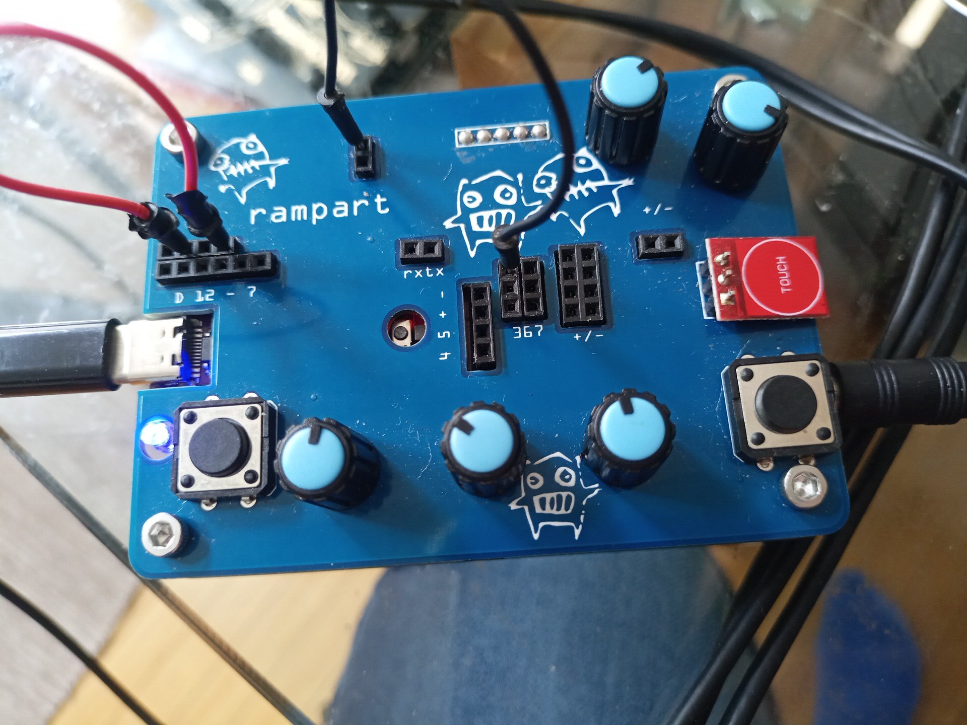
Connections overview

parts overview
| Section | Part | Function |
|---|---|---|
| 1 | 3.5 mm stereo | Audio/Clock in |
| 2 | Digital 12 - 7 | Digital i/o |
| 3 | touch pins | Signal from 13 |
| 4 | Digital 0/1 | TX/RX |
| 5 | Encoder | control |
| 6 | Volume | Vol + lowpass filter |
| 7 | usb | program / power |
| 8 | reset | restart rampart |
| 9 | pin 4/5/+/- | designed for oled displays |
| 10 | analog 3,6,7 | inputs used by rampart programs |
| 11 | +/- | positive voltage and ground |
| 12 | +/- | positive audio signal and ground |
| 13 | Touch | capacitive Touch button with led |
| 14 | led | signal on pin 13 |
| 15 | button | 15 and 16 are input buttons used in programs |
| abc | pots | analog controls (a0 to a2) used in rampart programs |
-
audio (right channel) & clock (left channel) input. Pocket-operator can be directly connected. The Clock comes out at 4 ( the rightmost pin, tx) and can be plugged into one of the inputs in section 10 (inputs 3, 6 or 7, rows of 2, top to bottom, ).
-
digital input/outputs. For bytebeats, 11 needs to be wired to 9 (second from left to 4th from left). That’s the only necessary change to get sound :) The headers 12 to 9 are doubled and digital pins 8 and 7 are single (the end of the bottom row in section 2). None of the pins but 11 and 9 are used by the bytebeats program.
audio out for bytebeats
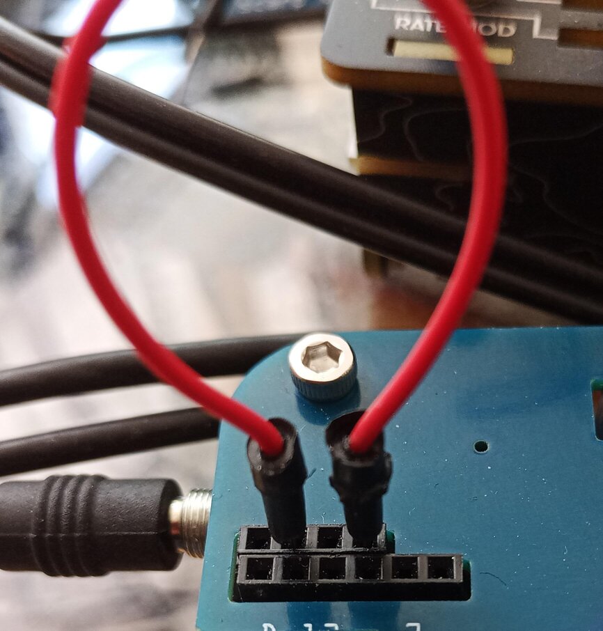
- these 2 vertically oriented pins are the output of the red touch button (labeled 13). You can insert into 3,6 or 7 (at 10). This creates a full positive voltage to the pin which will be averaged with the position of the pots (a b & c). So, if you connect as in the picture below, you will get an average of the pot on the leftmost and the signal on pin 3 (first 2 inputs, left to right on the column 367, labeled 10).
touch to cv3
You can also daisy chain that for fun 3 param hacking with the touch button.
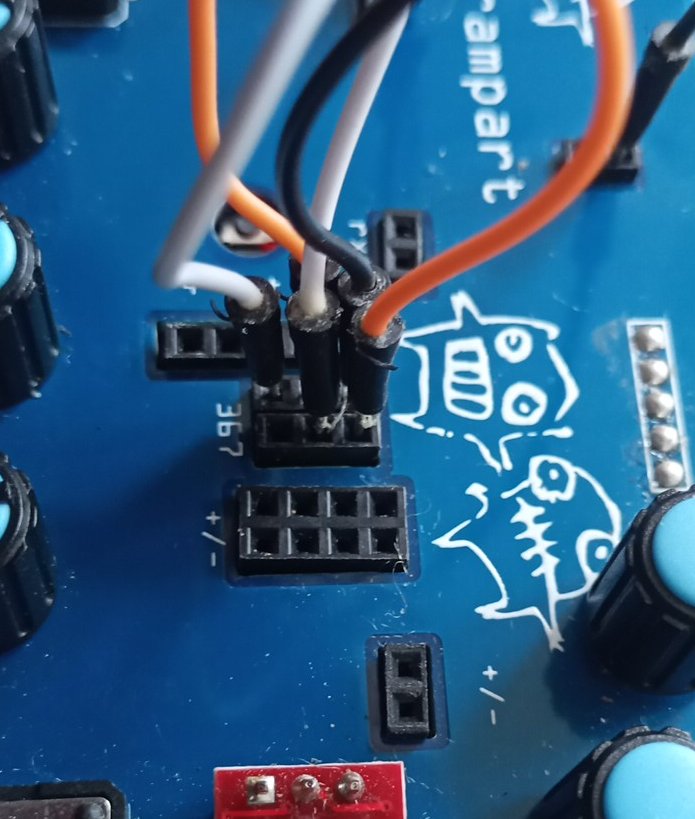
daisy chain 3,6,7
-
two pins rx and tx (receive and transmit) The clock signal from 1 goes to tx on the right pin at 4. For Bytebeats you can connect the rightmost pin from 4 (tx) to 3,6 or 7 to modulate the settings of pots a b & c ( the position of the pot and the input on 3-7 are averaged, input 3 with pot a, input 6 with pot b and 7 with c.)
-
encoder / button: a) turning will increase or decrease the frequency, starting on boot at 8000 HZ, steps of 64 HZ. b) Push and hold down and turn left, play backwards at increasing frequency; turn right and forwards increasing frequency (doubling). c) single click: bank 1 of formulas, double click: bank 2, triple click :bank 3
-
volume/filter it’s advisable to start bytebeats with this at 12 o’clock to avoid harsher high end. Will also mix the relative loudness of input from 1 vs. the ramparts internal audio.
-
usb power/programming
-
reset button, if rampart should hang which happens rarely, but can at higher frequencies
-
Two analog inputs (4&5) and + /- power. Not directly used in the bytebeats sketch. These are in the design to allow you to create a sketch that uses an I2C oled display. It’s been tested with with an SSD1306 using the adafruit drivers.
-
analog inputs 3, 6 and 7 ( to row 2 pins input 3, next row of 2, input 6, and finally 2 inputs to 7) used to modify bytebeats params a / b /c in addition to the pots labeled a b & c at the bottom.
-
+/- power columns ( a 2*4 header, all pins on the left are + 5v and all 4 pins on the right are ground) can be used, for instance, put a capacitor from + to inputs at 10 to create a contral voltage. Very fun with a 1uf Elko.
-
+/ - sides of the audio output. You can tap the output (+ is signal, - is common ground).
-
Touch button with LED, see 3
15/16. Left & Right buttons select previous and next program of bank
Bottom right, barely visible is the audio out. You can plug-in headphones, but turn down 6, vol. First. If you plug in stereo audio to the input, it will feed through but moving the encoder or pushing buttons will make noises. A PO or Scarp signal will be clean (split clock).
Multifunction Generator firmware
The functions encompass:
- a polyrythm generator
- a Generative Sequencer
- a Multimode Envelope
- an ADSR
- a burst generator
A brief overview:
Switch between patches by numerical click of the encoder button (in rapid succession).
Output is on pin 9 (or the audio output). Clock/Gate input is on pin 7. I haven’t tried, but one should be able to use the audio input and wire ‘rx’ to pin 7.
To patch into keep, use diode (1n4148, for instance) from the matrix to either an FM input (a/b) or the amplitude modulation input.
Given gate or trigger signals on 7 the following patches are available:
Polyrythm generator
Generate gate/triggers:
Each pot acts as a subdivision of the incoming clock. When a rhythm knob is fully CCW (0) no rhythm is set. Moving the rhythm knob CW, the first subdivision is every 16 beats. When the knob is fully CW, that is a subdivision of 1 and the polyrhythm will trigger every beat.
The logic mode is set using by turning the encoder: OR, XOR, NOR, AND are the modes.
Generative Sequencer
Generatve random CV on 16 steps.
- First pot sets the probability for ’this’ step
- pot 2 allows you to set the current step.
- Pot 3 sets the amplitude for the output (global, not per step).
To set some ‘refraining’ so that steps are less likely to update (more likely to repeat) use the left and right buttons.
Multimode Envelope
The pots set Attack, and Release values (third pot not implemented yet). Generates multiple envelope types: AR, ASR, SLOW, LFO which can be set using the encoder. LFO mode is looping. The curves for the envelopers can be set with left and right buttons: LOG, LINEAR, EXP.
ADSR
This envolope has the value of attack, delay and sustain on the pots and release on the encoder.
Use the right button to to switch looping mode on / off.
Burst generator
Generates 3 types of triggers, fade in, flat or fade out, set by using the buttons.
Pot one set the burst rate and pot two, the burst count.
The third pot sets the sequences ‘shape: fade in, flat, fade out, triangle or random.
That’s the long and short of it ;)