rampart abuse (and use)
An initial guide to Rampart, mainly bytebeats
Since rampart is more platform than any given instrument, this overview tries to cover ground that isnt’ just relevant to the bytebeats sketch.
But, we’ll start with which interface bits play a role in the default bytebeats sketch.
- 5, pushbutton and encoder: rotate to increase, decrease frequency. push and turn to double or halve freq. short button pushes (1,2 or 3) change the bank of programs (there are three)
- 6, volume/filter
- 15/16 are program back and forward buttons
- 10, controlvoltage inputs 3,6,7 which are averaged with to the controls …
- a b & c, being the 3 parameters of every bytebeat formula.
Play around :)
At the bottom of the page are firmware update instructions and initial info on how to program.
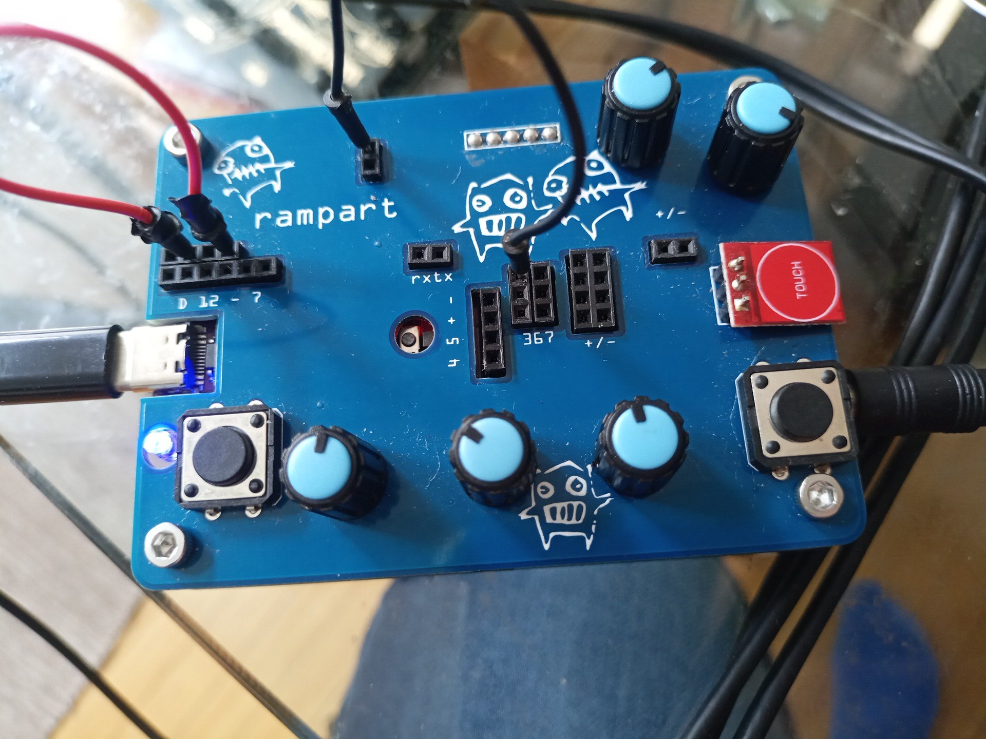
Connections overview

parts overview
| Section | Part | Function |
|---|---|---|
| 1 | 3.5 mm stereo | Audio/Clock in |
| 2 | Digital 12 - 7 | Digital i/o |
| 3 | touch pins | Signal from 13 |
| 4 | Digital 0/1 | TX/RX |
| 5 | Encoder | control |
| 6 | Volume | Vol + lowpass filter |
| 7 | usb | program / power |
| 8 | reset | restart rampart |
| 9 | pin 4/5/+/- | designed for oled displays |
| 10 | analog 3,6,7 | inputs used by rampart programs |
| 11 | +/- | positive voltage and ground |
| 12 | +/- | positive audio signal and ground |
| 13 | Touch | capacitive Touch button with led |
| 14 | led | signal on pin 13 |
| 15 | button | 15 and 16 are input buttons used in programs |
| abc | pots | analog controls (a0 to a2) used in rampart programs |
-
audio (right channel) & clock (left channel) input. Pocket-operator can be directly connected. The Clock comes out at 4 ( the rightmost pin, tx) and can be plugged into one of the inputs in section 10 (inputs 3, 6 or 7, rows of 2, top to bottom, ).
-
digital input/outputs. For bytebeats, 11 needs to be wired to 9 (second from left to 4th from left). That’s the only necessary change to get sound :) The headers 12 to 9 are doubled and digital pins 8 and 7 are single (the end of the bottom row in section 2). None of the pins but 11 and 9 are used by the bytebeats program.
audio out for bytebeats
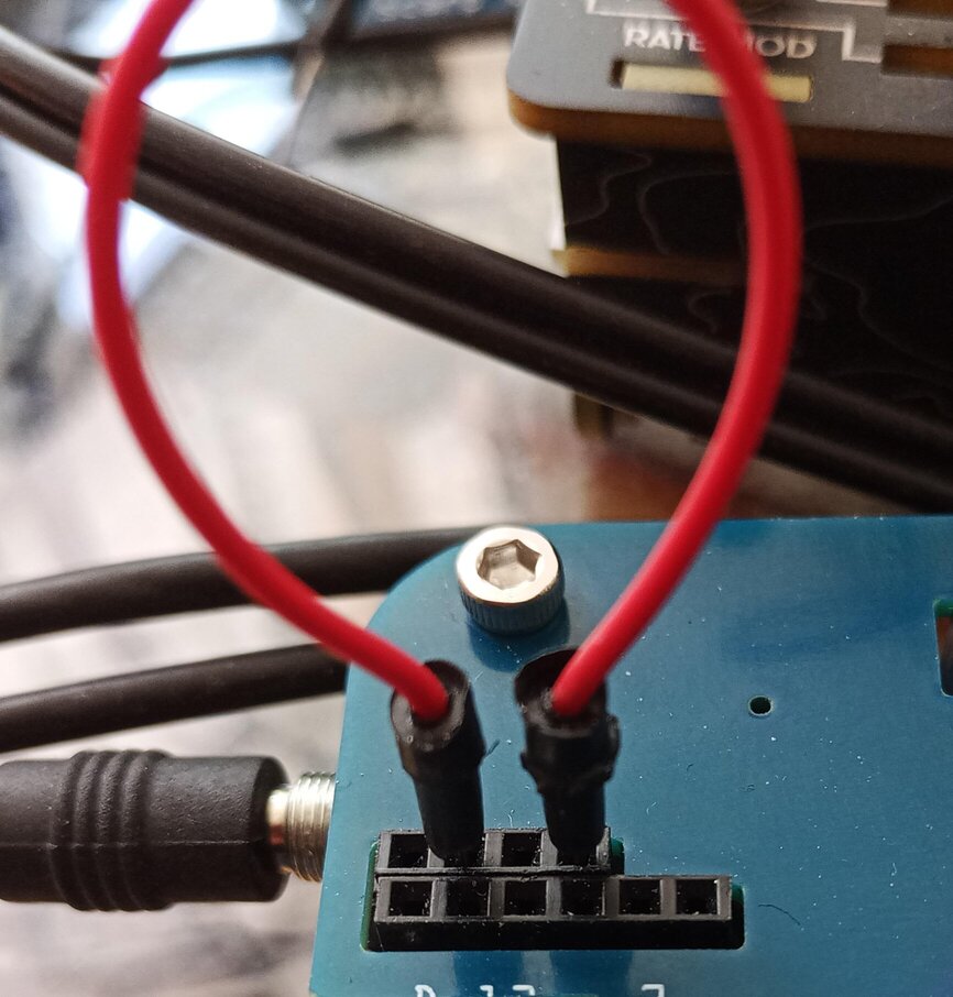
- these 2 vertically oriented pins are the output of the red touch button (labeled 13). You can insert into 3,6 or 7 (at 10). This creates a full positive voltage to the pin which will be averaged with the position of the pots (a b & c). So, if you connect as in the picture below, you will get an average of the pot on the leftmost and the signal on pin 3 (first 2 inputs, left to right on the column 367, labeled 10).
touch to cv3
You can also daisy chain that for fun 3 param hacking with the touch button.
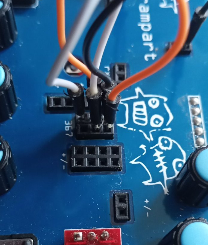
daisy chain 3,6,7
-
two pins rx and tx (receive and transmit) The clock signal from 1 goes to tx on the right pin at 4. For Bytebeats you can connect the rightmost pin from 4 (tx) to 3,6 or 7 to modulate the settings of pots a b & c ( the position of the pot and the input on 3-7 are averaged, input 3 with pot a, input 6 with pot b and 7 with c.)
-
encoder / button: a) turning will increase or decrease the frequency, starting on boot at 8000 HZ, steps of 64 HZ. b) Push and hold down and turn left, play backwards at increasing frequency; turn right and forwards increasing frequency (doubling). c) single click: bank 1 of formulas, double click: bank 2, triple click :bank 3
-
volume/filter it’s advisable to start bytebeats with this at 12 o’clock to avoid harsher high end. Will also mix the relative loudness of input from 1 vs. the ramparts internal audio.
-
usb power/programming
-
reset button, if rampart should hang which happens rarely, but can at higher frequencies
-
Two analog inputs (4&5) and + /- power. Not directly used in the bytebeats sketch. These are in the design to allow you to create a sketch that uses an I2C oled display. It’s been tested with with an SSD1306 using the adafruit drivers.
-
analog inputs 3, 6 and 7 ( to row 2 pins input 3, next row of 2, input 6, and finally 2 inputs to 7) used to modify bytebeats params a / b /c in addition to the pots labeled a b & c at the bottom.
-
+/- power columns ( a 2*4 header, all pins on the left are + 5v and all 4 pins on the right are ground) can be used, for instance, put a capacitor from + to inputs at 10 to create a contral voltage. Very fun with a 1uf Elko.
-
+/ - sides of the audio output. You can tap the output (+ is signal, - is common ground).
-
Touch button with LED, see 3
15/16. Left & Right buttons select previous and next program of bank
Bottom right, barely visible is the audio out. You can plug-in headphones, but turn down 6, vol. First. If you plug in stereo audio to the input, it will feed through but moving the encoder or pushing buttons will make noises. A PO or Scarp signal will be clean (split clock).
Firmware and Arduino
Arduino Sketches
To edit the sketches you can use the arduino ide.
- install the ide from https://www.arduino.cc/en/software (I still use the 1.8.19 version)
- install the board support https://github.com/dbuezas/lgt8fx#how-to-install
- install the support library EncoderButton from Philip Fletcher (-> Tools -> Manage Libraries)
- download the latest source code from https://github.com/poetaster/rampart/releases (or do a git clone if you use git)
- open up a sketch in the firmware directory ( for instance rampart3-bytebeat)
The currently most complete sketch is the rampart3-bytebeat sketch.
A number of Arduino sketches being updated include 2 synths (switch with button 3 on digital pin 2) which have 3 to 4 variable parts of the signal. Both sketches share the wavepacket object as 1st synth. One has PDResonant as second, one an FM synth as second synth.
So, Patch 1 is always a wavelet (based on the wavelet example with mozzi) synth and Patch 2 is an FM synth or PDResonant. Also still rough ideas.
This synth works well with Keep (moat), my analog synth and also with Bastl’s Kastle synth. I’ve also played it with Korg’s micro modular which works quiet well (in both directions).
I’ve included a granular synth without mozzi as an example and two versions of a ‘glitch synth’ from other sources modified to work with rampart.
Upgrading firmware with hex files
First ensure you have drivers installed if you’re on windows or mac. On linux you should not need to install a driver. A good reference for the usb drivers (which work form most arduino boards or the lgt in rampart): https://learn.sparkfun.com/tutorials/how-to-install-ch340-drivers/all
The most current firmware hex files will be included in this directory and can be flashed as follows
linux: the device will most probably be ttyUSB0 as below:
- install avrdude using package manager
- attach the rampart to usb
- execute: avrdude -c arduino -b 57600 -F -P /dev/ttyUSB0 -p atmega328p -U flash:w:rampart3-bytebeats.ino.hex
windows:
- having installed the driver, above
- install avrdude from https://github.com/avrdudes/avrdude/releases (windows x64, x86 or arm64)
- attach the rampart to usb
- execute command: wmic path Win32_SerialPort Where “Caption LIKE ‘%%COM%%’” Get Description, DeviceID
- note the DeviceID of the “USB Serial Device” which will be something like: “COM5”
- using the DeviceID you’ve noted, adapt the following command (here -PCOM5).
- in the directory where you placed the hex file execute: avrdude.exe -patmega328p -carduino -D -PCOM5 -b57600 -Uflash:w:rampart3-bytebeats.ino.hex
macintosh:
- install the usb driver for the rampart using instructions from : https://github.com/WCHSoftGroup/ch34xser_macos has a .pkg file you can install.
- install avrdude through MacPorts or Homebrew. (with home-brew it: brew install avrdude).
- attach the rampart to usb
- in a terminal execute: “ls /dev/tty*” and note names with tty.wch in them like : tty.wchusbserial1234
- from the directory where you downloaded the hex file execute: avrdude -c arduino -b 57600 -F -P /dev/tty.wchusbserial1234 -p atmega328p -U flash:w:rampart3-bytebeats.ino.hex