PT2399 hack
This began with me just wanting a quick and dirty echo for my billow. For recordings which are quite percussive I wanted some slapback.
Although I have a bunch of homegrown circuits using the PT2399, I also had a couple of reverb boards (bought 5 for 8 Euros) lying around for fast and dirty work. I remembered having seen someone document this hack. https://www.anexium.com/instruments/PT2399-Mods.html
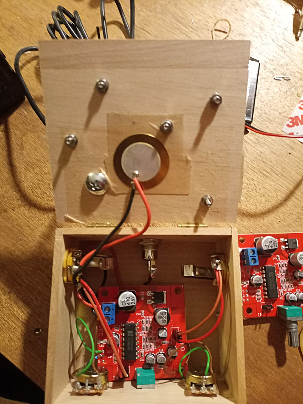
inside the hack
I quickly realized, well, why not just add the pickup and make it dual use. Yes, it just works. The pickups red wire / + is soldered to the 6mm jack tip and black/ground wire is soldered to 6mm sleeve. The signal is somewhat weak, but it works quite well. Then, I realized that I had modified the original idea in more than one way.
The linked doc from anexium is a good overview. However, it makes things more complicated than need be :) And is more dangerous than what I detail here. We’re going to apply the following circuit, S and G referring to markings on the board (see below the breadboard picture).

breadboard
The S and G inputs are highlighted as is the R27 resistor on the board pictured below:
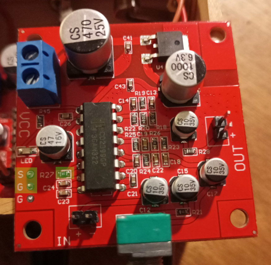
above
- Remove the SMD resistor R27
- The 100K pot, breadboard on the left, will have it’s leftmost (seen from the top/front) pin soldered to the “S” input on the left in the above image. I do this by soldering wire throught the S hole while the board is in a vice.
- The leftmost and center pins of this pot are bridged with a small piece of wire.
- The rightmost pin of this pot is connected to a “G” (ground) hole Via a 1K resistor, on the left in the above image. I solder the resistor directly through the G spot (:) I put the board in the vice, hold the soldering iron on the bottom of the hole and gently push the resistor through from the top.
Here a picture of the completed wiring.
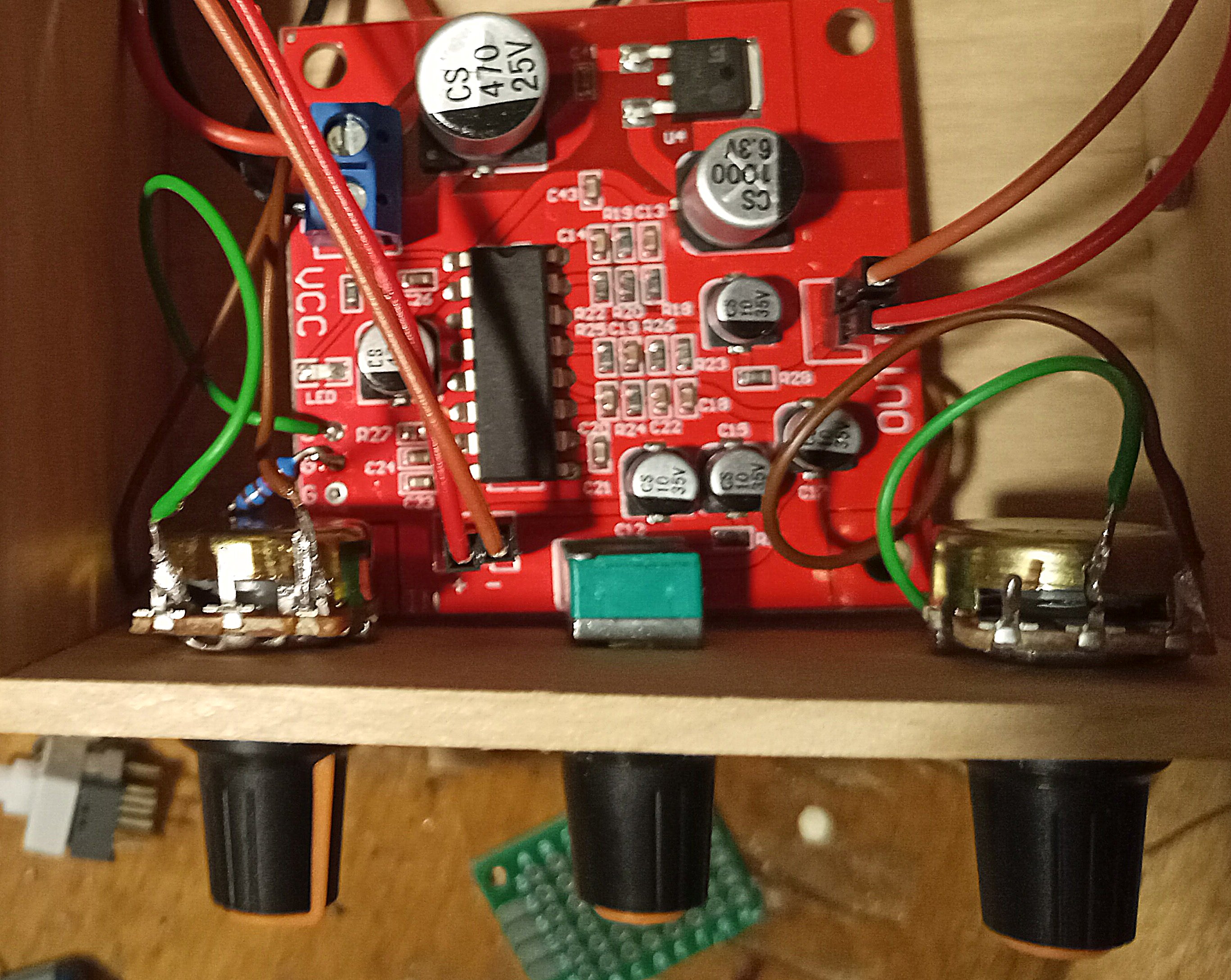
delay
On to the feedback:
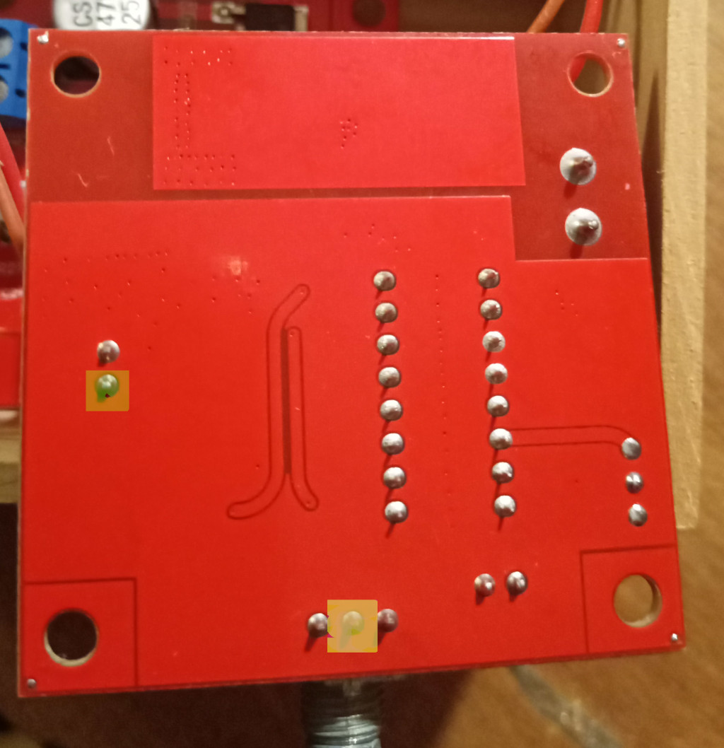
below
- The middle 100K pot on the breadboard will have it’s middle pin soldered to the middle pin of the pot on the board as seen at the bottom middle of the image below
- This pot will also have it’s right pin soldered to the + pin of the board output as seen at the left of the image below
Completed on the bottom.
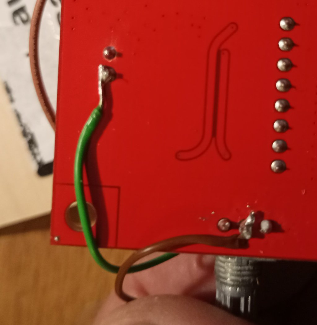
feedback
And that’s about it. As one can see the number of steps and the danger of soldering near the SMD cap are not an issue. And it sounds the same.
You can also just use the guide from anexium :) However, it is not necessary to solder the feedback knob via the SMD capacior. My way has the same effect without being in a difficult to solder position.