Building the keep
Introduction, notes on header height
Before we get on to the build, proper, a bit on the pin headers.
In recent builds, I’ve moved to elevating" the pin headers by extending" them. This makes placing pins easier.
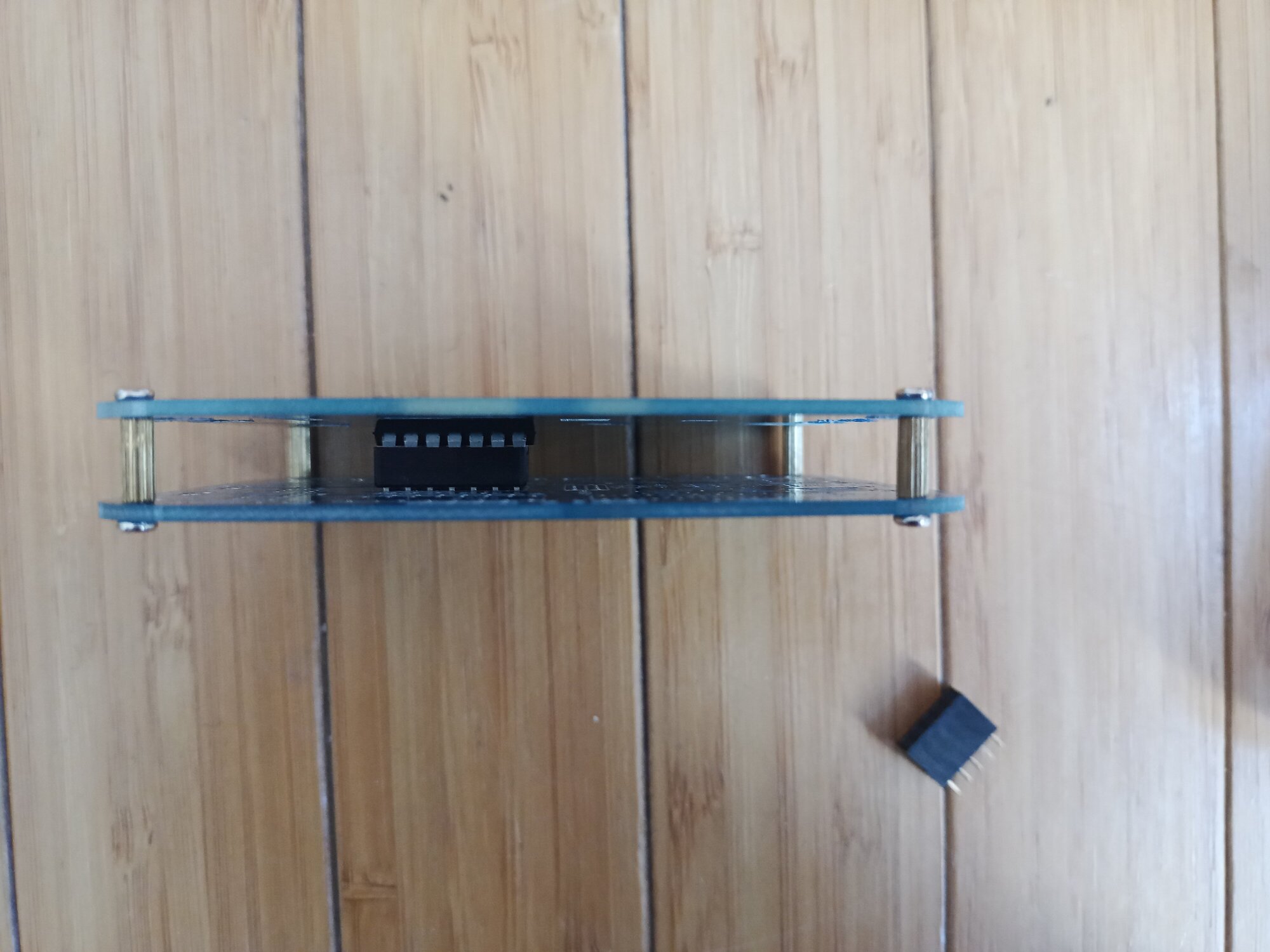
top mounted with 8mm spacers.
The IC on is slightly squeezed, isn’t it? Well, it doesn’t matter in practice, but …
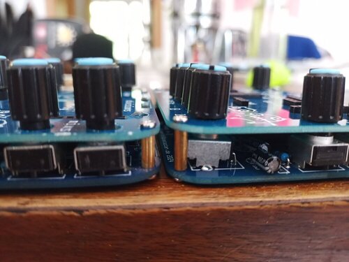
pin headers sunk
The middle matrix header, sitting flush with the bottom pcb. It’s 1mm about below the top of the top pcb.
This has turned in practice to be a bit pita. It’s also a pita on bastl’s kastle series.
the solution
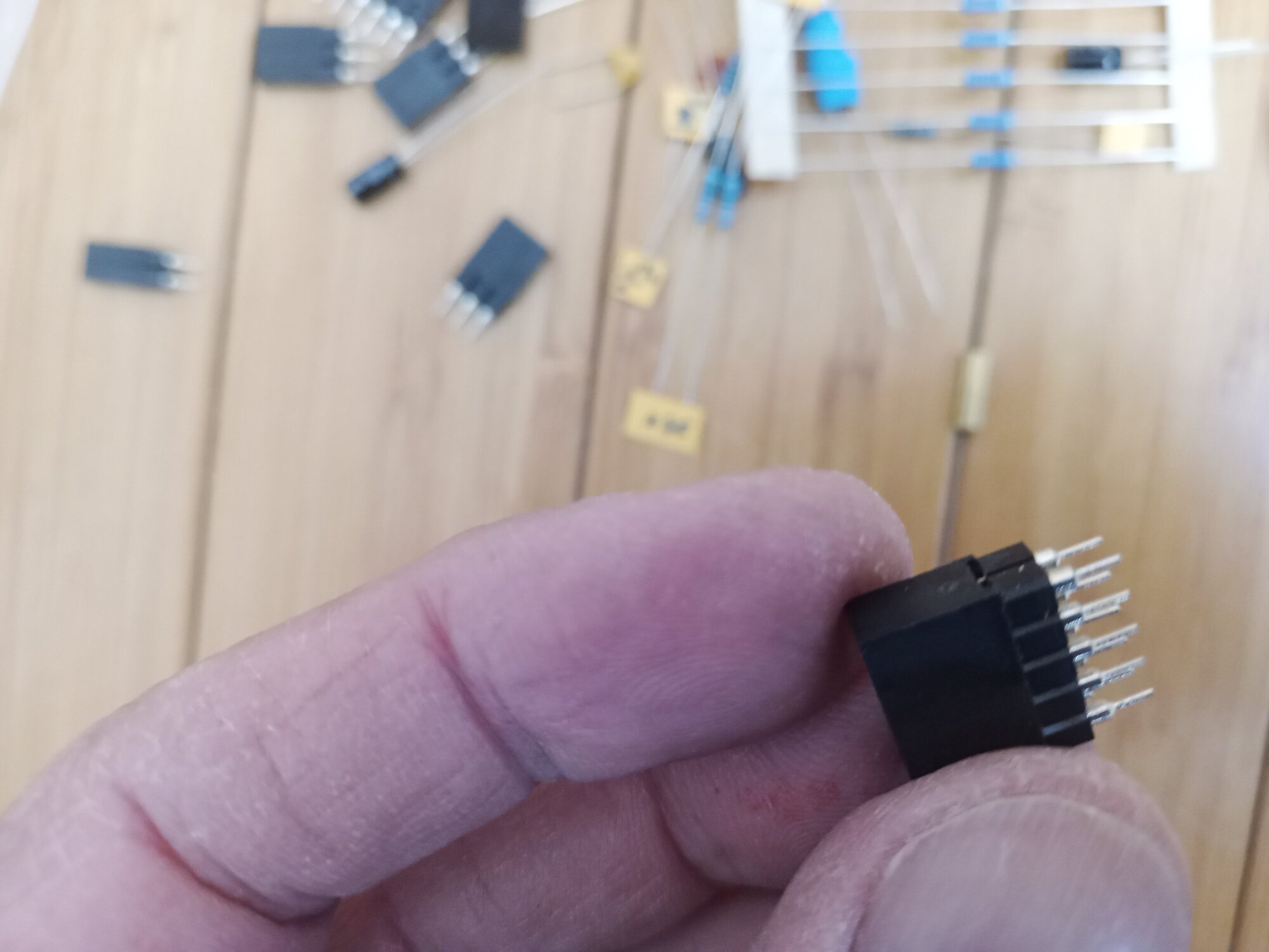
I discovered a simple fix, which is to add lower round headers as an extension.
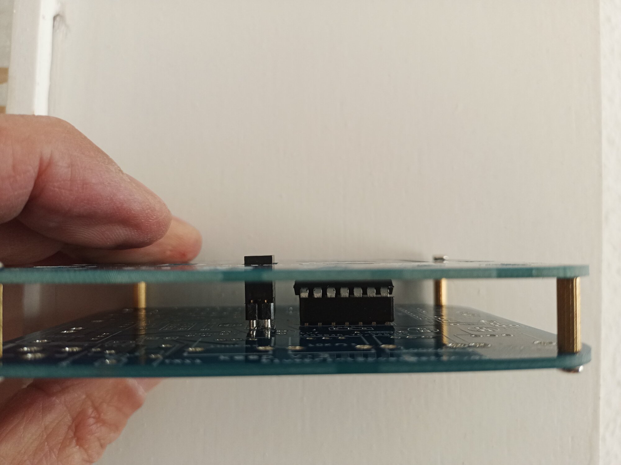
with 10 mm spacers
With a 10 mm spacer, they sit a bit more than 1 mm above the surface.
I find this easier to use, especially in the dark ;)
It also means the top pcb is not pressing down on the ICs. That wasn’t tragic, but tight.
Ok, get on with the build!
You’ll need the usual.
- Soldering iron,
- solder (I use .5mm solder),
- clippers,
- kneedle nose pliers (or similar)
- I need a magnifying glass
- good light.
- small screw drivers
- maybe a multimeter? I like em.
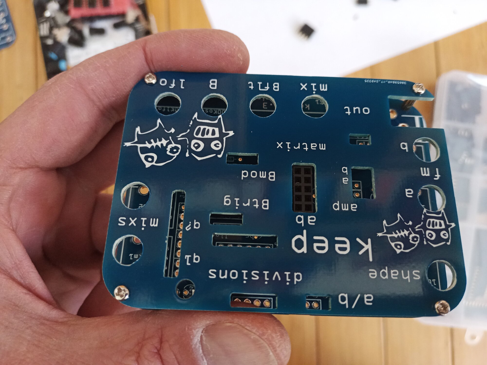
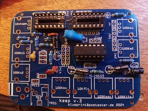
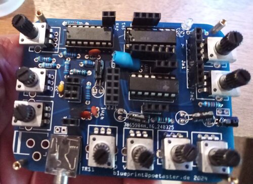
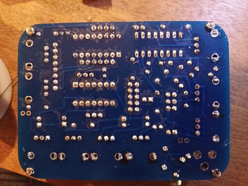
All parts are labeled on the bottom pcb and parts in the kit are labeled.
Start with the resistors.
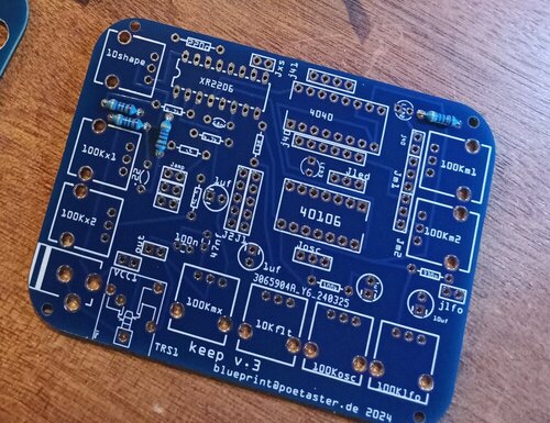
resistors

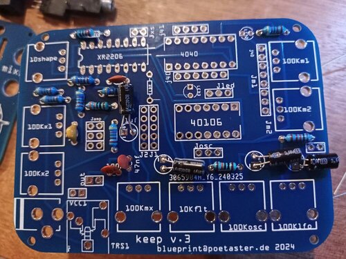
resistors & a cap
Then the capacitors. In this example I’ve exagerated the distance of the electrolytic caps, lying down.
The caps are labeld 683 for 68NF, 473 for 47NF, 223 for 22NF and 104 for 100NF. The electrolytic are simply 1 and 10 uF.
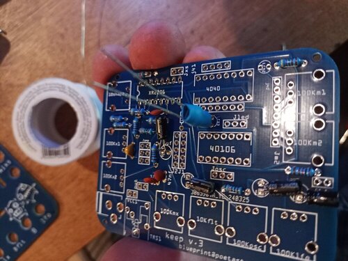
capacitors
You should make them lie down, but you shouldn’t bend them as far from the base as I have here. This is just exagerated for show :)
Bend not too close to the base of the elko, or you can damage the capacitor. But bend ’em.
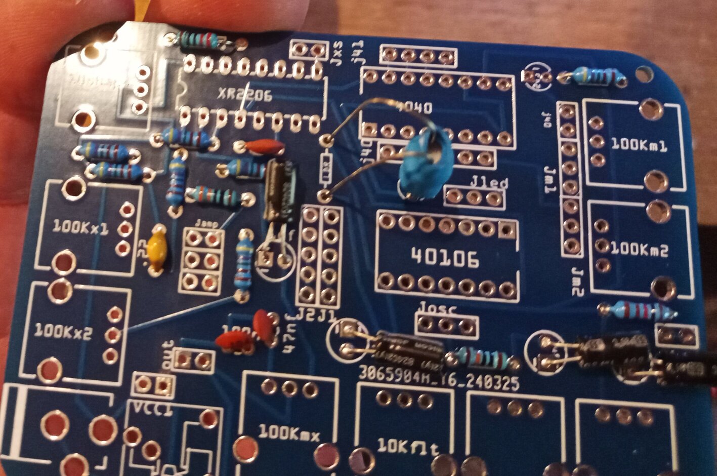
And on to the DIY vactrol
vactrol led side
Start by inserting the led side, long leg(+) LED3 sqare hole. Leave some wire for play (2 mm).
vactrol ldr side
Bend and insert the LDR side pins into the LDR marked holes. Pull each a small bit at a time till it sits as below.
vactrol ldr side
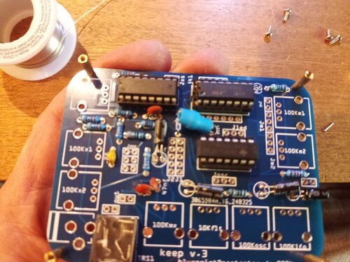
Now solder the IC sockets. Make sure to orient them with the open ends as on the board. Then you won’t have issues orienting the ICs. Then, insert the ICs. I use the slightly squeeze and wiggle technique.

ics insterted
Never really push until all pins are well in. I just squeeze wiggle between thumb and forefinger. Note the orientation of the ICs.
Take a minute to place and solder the audio jack. It can take a little wiggle. Be sure the pins are aligned with the holes before you push/wiggle down.
One limitation of using fritzing to do pcbs is that you have no slots, and large holes are not always a good solution. The audio jacks almost always sit a bit crooked.
brass spacers inserted
Now we take the screws and spacers and attach them to the bottom pcb …. and attach the top pcb. two screws are enough, top left, bottom right.
inserting headers
Start with the 5x2 matrix header and the 3 amp, a and b headers.
Then you can turn it over (use a business card or finger to hold the headers.
Solder the pins when you have the pins lined up more or less centered in the soldering holes. Should be fairly easy.
all the headers soldered
If something seems a bit tight, wiggle! If it doesn’t move, you can use a small file.
This should not happen, but sometimes a part is faulty, or I’ve sent you the wrong top pcb. :smiley:
There’s nothing active on the top layer and if you are gentle you won’t see it was filed.
pots inserted
It’s time to mount the pots. Remove the top pcb and place the pots. Don’t solder yet!

checking the pots all move
Place the top pcb on top again, and check the seating of the pots.
The pots should all turn freely. You’ll have to generally push the pots down toward the outside of the pcb.
one pin of pot soldered
While holding a pot in place so that the back feet are flush, solder one the three small pins.
Take a look from the top, check the turn. If it’s not flush on it’s back feet, you can adjust heating up the one pin you soldered.
When it sits, solder the rest.
For the weight bearing large supports, I clip first an then solder to keep from having the high bump you get if you solder them and then clip.
clip solder
Below, you can see pots that are NOT sitting correctly. So they ’lean’ into the device. It’s not tragic, but not nice either. Take your time getting each pot to sit.
pots not sitting down on the back legs!
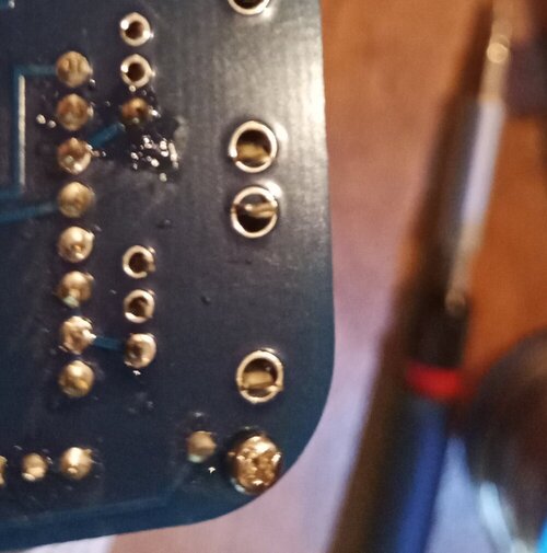
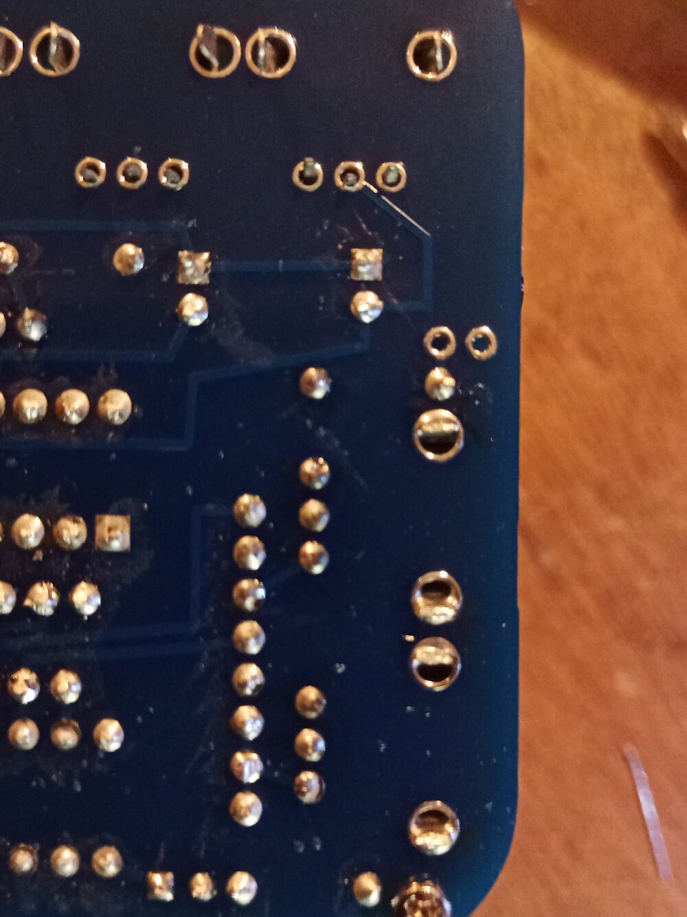
all the solder are belong to us
Now check your solders. Notice the lower right side. I didn’t finish all the pots.
Left me scratching my head when I did the ’test'.
barrel jack adapter in....
Now we solder in the barrel jack power socket thingy. I only do a bit of solder, clip the big legs and then add more solder.
Keeps everything close to the board.
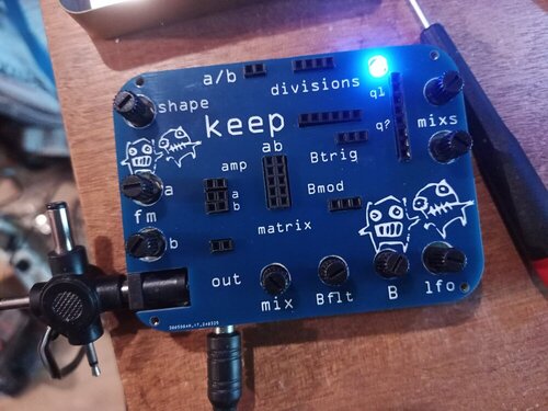
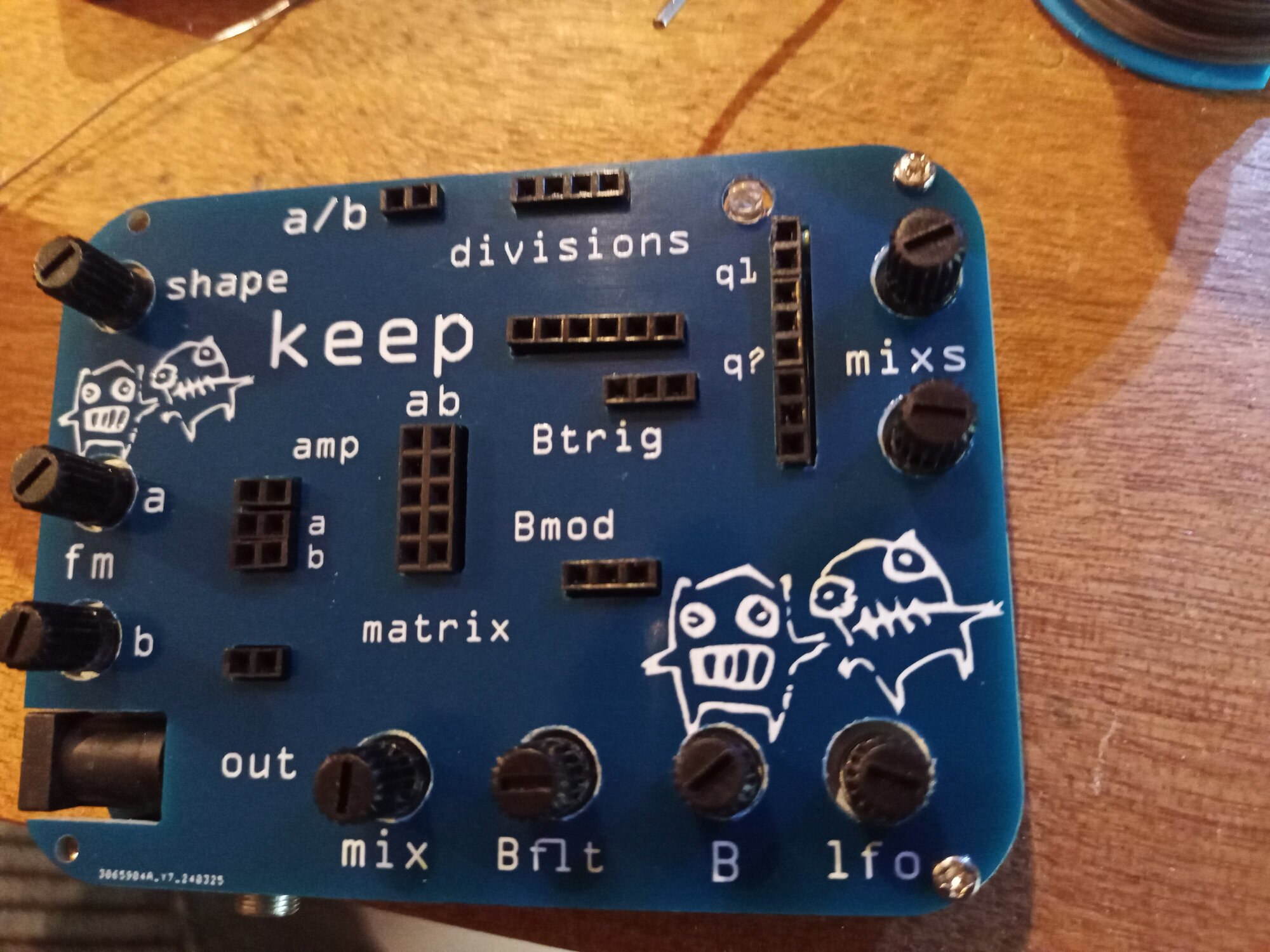
THE TEST
Let’s plug in the power and audio, and see what happens! First good sign is a blinking led. test the lfo to see if it blinks faster :)
You should also hear a tone from the XR2206. Turn the a ‘fm’ knob to see if the pitch changes.
If all’s well, you can put on the pot knobs!
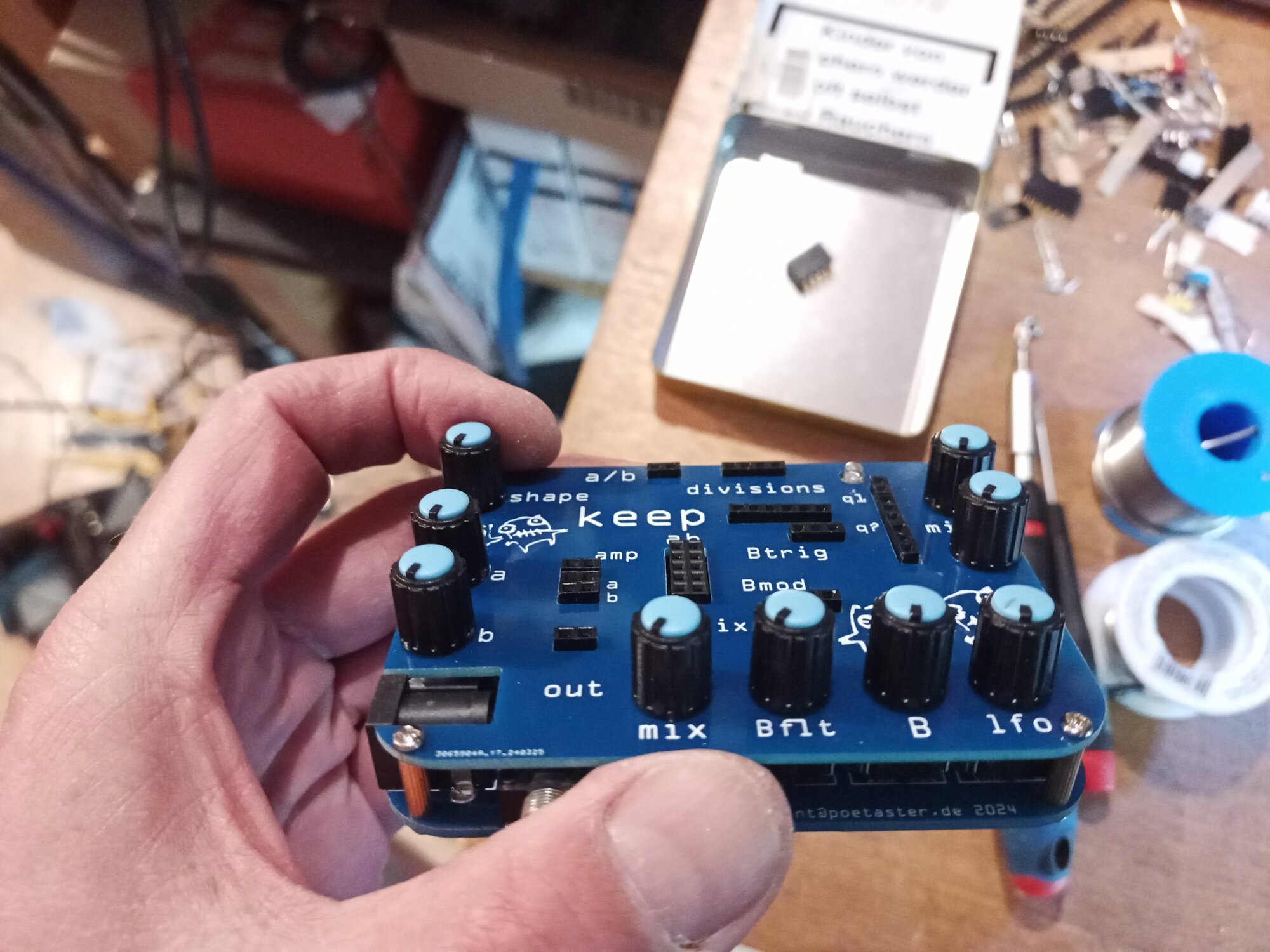
pot knobs
Don’t push them too hard, they don’t need to click. Should just sit close the board. If it won’t go down, pushing it too hard could damage the pot.
And yes. You are a rock star.
Now get out the pins and make some funny music!