banners
wavey!
banners
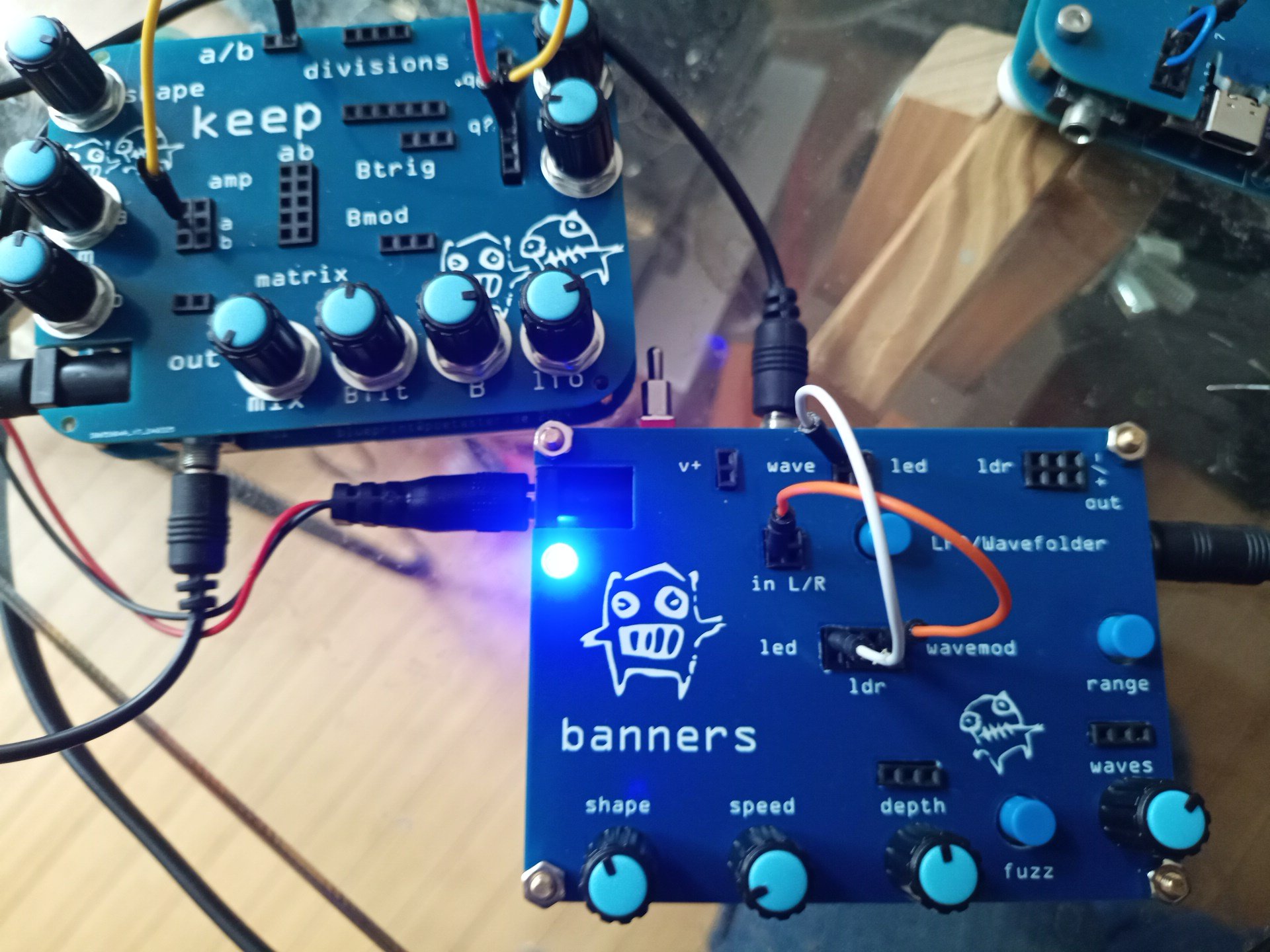
Banners is a wavefolder with lfo for modulation. The lfo can be used without folding. There is an extra vactrol for futzing about!
There are three stages of folding with the last being ‘fuzz’ (optional via a switch), so not symtrical. As with most folders, it requires symetry on the input, so sine of triangle waves. Other input gets messy :)
Unlike most folders, banners uses a quad op amp for both the folder and a second one for the lfo. The conventional wavefolder uses oposing saturating npn/pnp transistors. It’s simpler with an op amp :)
A brief overview of functions and input pins can be found at the bottom of the page….
Here a view of the oscilloscope of a melody from the keep through banner. This is just clean 2 times folding without fuzz.
Kastle in minimal mode through banners. I switch back and forth between symetrical and fuzz folding.
This is the breadboard view from fritzing.

banners breadboard
https://github.com/poetaster/banners
The switch between LFO and Wave modes can make noise if you tap on it in one or the other mode. The LFO mode is also louder. I’m still trying to work out how to build in a better type of switch.
You can purchase a built banners from me for 86 euros. DIY kits are are 68 euros.
Pin inputs & abuse
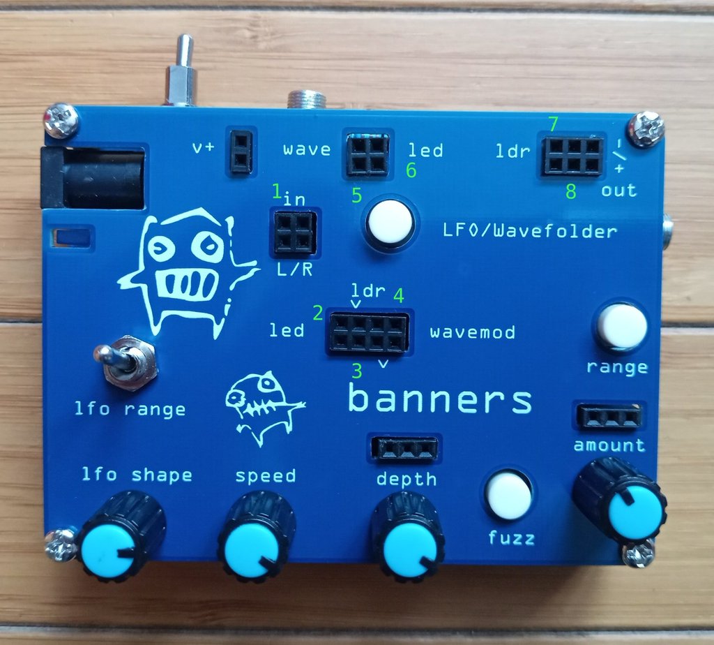
banners inputs
- Left and Right inputs from the 3.5mm jack above, or free input from another device via pin
- LED input. The led is generally driven by the LFO to the left, which modifies the ‘amount of wavemod’. You can, for instance, modify this by patching R from 1 into 2 led to get a sort of chorus effect as the audio input interferes with the LFO.
- The input to the ldr and next to it the output. Usually the wavemod (controlled by amount). You can patch signlas in here. Though it’s more constructive to patch them into amounts far right input (input to the pot, so you can ‘mix’
- The wave form modulator, usually just a linear voltage controlled by amount. This is direct, without the modulation via the LFO if you patch through the LDR or amount inputs.
- This is the wave being folded. Usually the left channel from the input. You can do BOTH. In the example below I add a waveform (an lfo) to the L input to get a more complex wave to fold.
- The independant VACTROL! This is just extra. Put a signal into 6 to controll the output on 8. for the
- VACTROL input
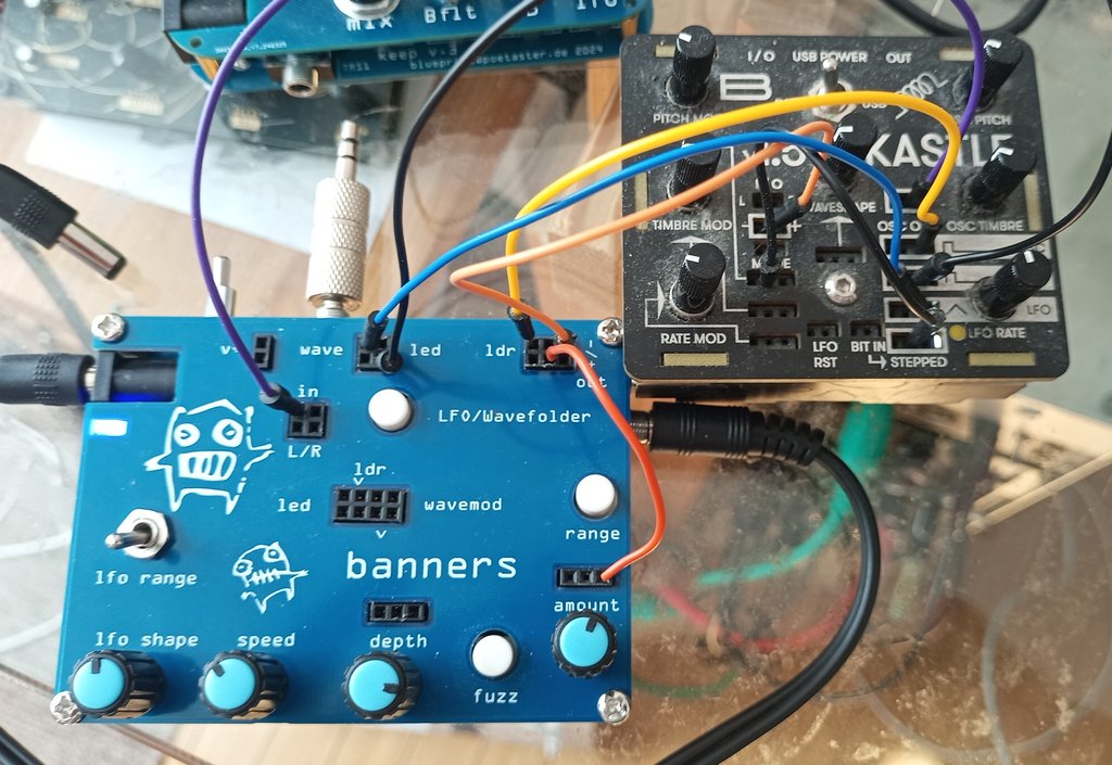
banners &kastle via pins
In this example, the OSC output from kastle is patched into L (1), so the main signal to bend. But, kastle’s lfo is pushed to wave (5) directly (blue cable) so we get a modulated mixed input. The square output of the kastle lfo drives the led (6) and the kastle OSC ouput is pushed via 7/8 LDR to the input of ‘amount’.
Ok. A somewhat complicated example :)